Woes with a 2004.5 LLY Dmax repeated P0089 Fuel pressure regulator codes.

Is brown/white a typo? ppl/white would be the wire you want. Also, that 3 wire connector you show in post #151 is not for the FPR. FPR is only 2 wire- ppl/white and yellow. Maybe that 3 wire is the fuel press sensor, but wire colors don't match...not that they always do.

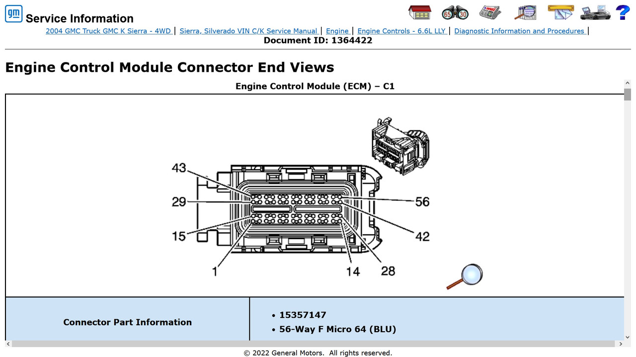
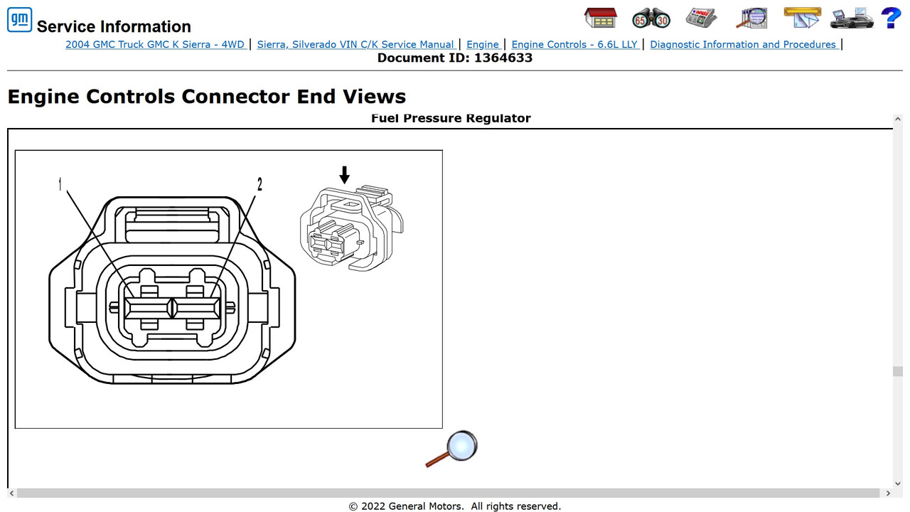
As for repeat FPR failures, the only other thing I can think of that would cause it would be a voltage spike. They should have a diode internally to protect it, but not certain. I think a voltage drop test is the next thing to check. With both plugged in, backprobe and put one meter lead on PCM terminal #40 and the other on terminal #1 of the FPR. Key on, should not read over .2V, if so there's hi resistance in that circuit. I'll post pics of the connector terminal ID's for the FPR and the PCM

And yes that vibration you feel is the PWM.

Odd that you feel the PWM with the KOEO. Should only be active with the engine running. Maybe the fuel press sensor is causing it to run constantly to bleed off the high rail pressure. I'll have to dig into this more.

 
Is brown/white a typo? ppl/white would be the wire you want. Also, that 3 wire connector you show in post #151 is not for the FPR. FPR is only 2 wire- ppl/white and yellow. Maybe that 3 wire is the fuel press sensor, but wire colors don't match...not that they always do.

It goes from 3 wires to 2, the black ground ends up in a shunt.

What do you think about the 11.66 volts at the regulator (unplugged), is it too low ?
And when I plug in the regulator it drops to 2.2 volts.


EDIT: The brown white stripe I am referencing might actually be a faded purple white stripe.
 
Last edited:
It goes from 3 wires to 2, the black ground ends up in a shunt.

What do you think about the 11.66 volts at the regulator (unplugged), is it too low ?
And when I plug in the regulator it drops to 2.2 volts.


EDIT: The brown white stripe I am referencing might actually be a faded purple white stripe.
Wasn't aware there was a jumper.

11.6 is a bit low, but 2 possibilities: low batt voltage at the batt or circuit resistance is pulling it down and then even more when a load is put on it

**the brown white is what through me a loop.
 
Wasn't aware there was a jumper.

11.6 is a bit low, but 2 possibilities: low batt voltage at the batt or circuit resistance is pulling it down and then even more when a load is put on it

**the brown white is what through me a loop.

Batteries show 12.47 and they are about 16 months old. Nov. 2020
They appear healthy, started the truck no problem this winter after sitting a week.
 
ok then. If batts are at 12.5 then that's almost a full volt drop. Need a voltage drop on just that circuit I mentioned above. If there's a short, that might be why it keeps eating FPR. And might also explain why rail press is so high.
 
I'm pretty sure the purple/white is the pwm output, and you are reading the average voltage. You need to scope it, meter isn't going to cut it.
 
Put the used ECM in, FPR vibrates with ECM also.
Checked voltage on at C10 of the big connector by the L/S valve cover it fluctuates between 11.5 and 11.8 volts.
At the connector where it plug into the FPR it is a steady 11.6 volts.
Shouldn't it be the same as the reading at the big connector ?
 
It's pwm, so you would have to check it with a scope.
 
It's not the same as using a scope, but it's useful in other ways. I'm going to post up some of the stuff that was lost from DRP.
 
DTC P0089
Circuit Description
The engine control module (ECM) uses commanded fuel pump flow to determine a desired fuel rail pressure (FRP). The actual fuel pressure is monitored using the FRP sensor. If the FRP sensor indicates a pressure more than 20 MPa greater than desired, DTC P0089 will set.

DTC Descriptor
This diagnostic supports the following DTC:

DTC P0089 Fuel Pressure Regulator Performance

Conditions for Running the DTC
  • DTCs P0192, P0193, P0642 or P0643 are not set.
  • The ignition is ON.
Conditions for Setting the DTC
  • The difference between actual and desired FRP is more than 20 MPa.
  • Commanded fuel pump flow is 100 mm³/second or less.
Action Taken When the DTC Sets – California
  • The control module illuminates the malfunction indicator lamp (MIL) when the diagnostic runs and fails.
  • The control module records the operating conditions at the time the diagnostic fails. The control module stores this information in the Freeze Frame/Failure Records.
Action Taken When the DTC Sets – Federal
  • The control module stores the DTC information into memory when the diagnostic runs and fails.
  • The malfunction indicator lamp (MIL) will not illuminate.
  • The control module records the operating conditions at the time the diagnostic fails. The control module stores this information in the Freeze Frame/Failure Records.
  • The driver information center, if equipped, may display a message.
Conditions for Clearing the MIL/DTC – California
  • The control module turns OFF the malfunction indicator lamp (MIL) after 3 consecutive ignition cycles that the diagnostic runs and does not fail.
  • A current DTC, Last Test Failed, clears when the diagnostic runs and passes.
  • A history DTC clears after 40 consecutive warm-up cycles, if no failures are reported by this or any other emission related diagnostic.
  • Use a scan tool in order to clear the MIL and the DTC.
Conditions for Clearing the DTC – Federal
  • A current DTC Last Test Failed clears when the diagnostic runs and passes.
  • A history DTC clears after 40 consecutive warm-up cycles, if no failures are reported by this or any other emission related diagnostic.
  • Use a scan tool in order to clear the DTC.
Diagnostic Aids
There are no driveability concerns associated with the FRP regulator unless a DTC is present. The most likely cause of this DTC is a sticking FRP regulator.

If the fuel system pressure is actually too high, a fuel knock and smoke condition will exist.

Test Description
The number below refers to the step number on the diagnostic table.

  1. DTC P0090 is a current flow problem in the FRP regulator circuit. This incorrect current draw could lead to incorrect fuel pressure. This hardware problem should be diagnosed before the performance DTC is checked.


Step​
Action​
Values​
Yes​
No​
1​
Did you perform the Diagnostic System Check – Engine Controls?​
—​
Go to Step 2​
2​
  1. Turn ON the ignition, with the engine OFF.
  2. Observe the Actual Fuel Rail Pressure parameter with a scan tool.
Is the Actual Fuel Rail Pressure parameter within the specified range?​
1.1–1.4 MPa​
Go to Step 3​
Go to Step 7​
3​
Did DTC P0090 also set?​
—​
Go to DTC P0090​
Go to Step 4​
4​
Did DTC P1093 also set?
—​
Go to DTC P1093​
Go to Step 5​
5​
  1. Start and run the engine at 2,000 RPM.
  2. Observe the Actual Fuel Rail Pressure parameter and the Desired Fuel Rail Pressure parameter with a scan tool.
Does the scan tool display a pressure difference more than the specified value?​
20 MPa​
Go to Step 11​
Go to Step 6​
6​
  1. Start and idle the engine.
  2. Perform the following test at idle and at 2,000 RPM:
    • Change the fuel pressure with a scan tool, incrementing through the entire fuel pressure range.
    • Observe the actual vs desired fuel pressures at each fuel pressure level.
Does the fuel pressure increment and stabilize through the entire fuel pressure range, with actual and desired fuel pressure within 2 MPa of each other at every fuel pressure?
—​
Go to Diagnostic Aids​
Go to Step 11​
7​
  1. Disconnect the fuel rail pressure sensor.
  2. Observe the Actual Fuel Rail Pressure parameter with a scan tool.
Does the Actual Fuel Rail Pressure measure more than the specified value?
175 MPa​
Go to Step 10​
Go to Step 8​
8​
Test the fuel rail pressure sensor signal circuit for a short to ground. Refer to Circuit Testing and Wiring Repairs in Wiring Systems.
Did you find and correct the condition?
—​
Go to Step 12​
Go to Step 9​
9​
Replace the engine control module (ECM). Refer to Engine Control Module Replacement.
Did you complete the replacement?
—​
Go to Step 12​
—​
10​
Replace the fuel rail pressure sensor. Refer to Fuel Injection Fuel Rail Fuel Pressure Sensor Replacement.
Did you complete the replacement?
—​
Go to Step 12​
—​
11​
Replace the FRP regulator. Refer to Fuel Pressure Regulator Replacement.
Did you complete the replacement?​
—​
Go to Step 12​
—​
12​
  1. Clear the DTCs with a scan tool.
  2. Turn OFF the ignition for 30 seconds.
  3. Start the engine.
  4. Operate the vehicle within the Conditions for Running the DTC.
Does the DTC fail this ignition?​
—​
Go to Step 2​
Go to Step 13​
13​
With a scan tool, observe the stored information, Capture Info.
Does the scan tool display any DTCs that have not been diagnosed?​
 
While the scanner is connected, check the engine RPM data, key on engine off. If it is a number other than zero, report back, even if it's 1 or -1. If it's zero, disregard.
 
When it sets the code, take a picture of the freeze frame data. Every time a code sets, it takes a snapshot of the data at the moment that it set the code. Don't clear the code, but post the data.
 
It's not the same as using a scope, but it's useful in other ways. I'm going to post up some of the stuff that was lost from DRP.

Is this useful, just grabbed it, the bump is when I gave it throttle


DTC P0089
Circuit Description
The engine control module (ECM) uses commanded fuel pump flow to determine a desired fuel rail pressure (FRP). The actual fuel pressure is monitored using the FRP sensor. If the FRP sensor indicates a pressure more than 20 MPa greater than desired, DTC P0089 will set.

DTC Descriptor
This diagnostic supports the following DTC:

DTC P0089 Fuel Pressure Regulator Performance

Conditions for Running the DTC
  • DTCs P0192, P0193, P0642 or P0643 are not set.
  • The ignition is ON.
Conditions for Setting the DTC
  • The difference between actual and desired FRP is more than 20 MPa.
  • Commanded fuel pump flow is 100 mm³/second or less.
Action Taken When the DTC Sets – California
  • The control module illuminates the malfunction indicator lamp (MIL) when the diagnostic runs and fails.
  • The control module records the operating conditions at the time the diagnostic fails. The control module stores this information in the Freeze Frame/Failure Records.
Action Taken When the DTC Sets – Federal
  • The control module stores the DTC information into memory when the diagnostic runs and fails.
  • The malfunction indicator lamp (MIL) will not illuminate.
  • The control module records the operating conditions at the time the diagnostic fails. The control module stores this information in the Freeze Frame/Failure Records.
  • The driver information center, if equipped, may display a message.
Conditions for Clearing the MIL/DTC – California
  • The control module turns OFF the malfunction indicator lamp (MIL) after 3 consecutive ignition cycles that the diagnostic runs and does not fail.
  • A current DTC, Last Test Failed, clears when the diagnostic runs and passes.
  • A history DTC clears after 40 consecutive warm-up cycles, if no failures are reported by this or any other emission related diagnostic.
  • Use a scan tool in order to clear the MIL and the DTC.
Conditions for Clearing the DTC – Federal
  • A current DTC Last Test Failed clears when the diagnostic runs and passes.
  • A history DTC clears after 40 consecutive warm-up cycles, if no failures are reported by this or any other emission related diagnostic.
  • Use a scan tool in order to clear the DTC.
Diagnostic Aids
There are no driveability concerns associated with the FRP regulator unless a DTC is present. The most likely cause of this DTC is a sticking FRP regulator.

If the fuel system pressure is actually too high, a fuel knock and smoke condition will exist.

Test Description
The number below refers to the step number on the diagnostic table.

  1. DTC P0090 is a current flow problem in the FRP regulator circuit. This incorrect current draw could lead to incorrect fuel pressure. This hardware problem should be diagnosed before the performance DTC is checked.


Step​
Action​
Values​
Yes​
No​
1​
Did you perform the Diagnostic System Check – Engine Controls?​
—​
Go to Step 2​
2​
  1. Turn ON the ignition, with the engine OFF.
  2. Observe the Actual Fuel Rail Pressure parameter with a scan tool.
Is the Actual Fuel Rail Pressure parameter within the specified range?​
1.1–1.4 MPa​
Go to Step 3​
Go to Step 7​
3​
Did DTC P0090 also set?​
—​
Go to DTC P0090​
Go to Step 4​
4​
Did DTC P1093 also set?
—​
Go to DTC P1093​
Go to Step 5​
5​
  1. Start and run the engine at 2,000 RPM.
  2. Observe the Actual Fuel Rail Pressure parameter and the Desired Fuel Rail Pressure parameter with a scan tool.
Does the scan tool display a pressure difference more than the specified value?​
20 MPa​
Go to Step 11​
Go to Step 6​
6​
  1. Start and idle the engine.
  2. Perform the following test at idle and at 2,000 RPM:
    • Change the fuel pressure with a scan tool, incrementing through the entire fuel pressure range.
    • Observe the actual vs desired fuel pressures at each fuel pressure level.
Does the fuel pressure increment and stabilize through the entire fuel pressure range, with actual and desired fuel pressure within 2 MPa of each other at every fuel pressure?
—​
Go to Diagnostic Aids​
Go to Step 11​
7​
  1. Disconnect the fuel rail pressure sensor.
  2. Observe the Actual Fuel Rail Pressure parameter with a scan tool.
Does the Actual Fuel Rail Pressure measure more than the specified value?
175 MPa​
Go to Step 10​
Go to Step 8​
8​
Test the fuel rail pressure sensor signal circuit for a short to ground. Refer to Circuit Testing and Wiring Repairs in Wiring Systems.
Did you find and correct the condition?
—​
Go to Step 12​
Go to Step 9​
9​
Replace the engine control module (ECM). Refer to Engine Control Module Replacement.
Did you complete the replacement?
—​
Go to Step 12​
—​
10​
Replace the fuel rail pressure sensor. Refer to Fuel Injection Fuel Rail Fuel Pressure Sensor Replacement.
Did you complete the replacement?
—​
Go to Step 12​
—​
11​
Replace the FRP regulator. Refer to Fuel Pressure Regulator Replacement.
Did you complete the replacement?​
—​
Go to Step 12​
—​
12​
  1. Clear the DTCs with a scan tool.
  2. Turn OFF the ignition for 30 seconds.
  3. Start the engine.
  4. Operate the vehicle within the Conditions for Running the DTC.
Does the DTC fail this ignition?​
—​
Go to Step 2​
Go to Step 13​
13​
With a scan tool, observe the stored information, Capture Info.
Does the scan tool display any DTCs that have not been diagnosed?​

So right now for #5 is Yes goto 11
11 is replace FPR, I know FPR is bad.
If I replace FPR it will be ok... for awhile then it goes to shit again.
Something is cooking these FPR's.
 
That's a pretty big difference between desired and actual, with a lot of flucuation.
 
You need to backprobe every ECM and GPCM ground with the engine running, and verify zero voltage. I'm thinking that the fuel system problems are actually a symptom, and not the root cause. I'm thinking that something is not getting a good ground, and is back feeding through the low ref circuit in the ECM. Get the RPM data I asked for earlier, I'm playing a hunch.
 
While the scanner is connected, check the engine RPM data, key on engine off. If it is a number other than zero, report back, even if it's 1 or -1. If it's zero, disregard.

RPM is 0 KOEO
FPR desired is 42 actual is 1
 
Ok. Post up the freeze frame data. It's usually a button on the screen with the code display.
 
Back
Top